Welcome! This is your first post. Edit or delete it, then start blogging!
Author: Reaz Wasifur Rahman
-

Stock Portfolio Tracker: Java GUI & Spring Boot API
Github repository for JAVA GUI: https://github.com/reazwrahman/stock-manager-gui
Github repository for Spring Boot REST API: https://github.com/reazwrahman/stock-manager-api
API is self-hosted at: https://stock-manager.reaz-projects.uk/usage
A quick 2 minutes demo: https://youtu.be/sXTsvaIcSoE?si=GExVt1zk8LA-qmLY
I built this stock portfolio tracker to solve a problem that has been on my mind for a long time – trying to see all my investments in one place. Like many casual investors, I had stocks scattered across Robinhood, Vanguard, and other platforms, making it tough to get a complete picture of each stock’s performance in comparison to others.
My solution has two main parts: a Java desktop app with a simple GUI where I can manually enter my stock details, and a Spring Boot API that does the backend calculations. When I input a stock, the backend grabs real-time price data and calculates my returns. I added some features like an in-memory cache to avoid hammering external APIs and implemented multithreading to handle lots of stock requests simultaneously without slowing things down.
I designed it with future expansion in mind: both components heavily use various creational, structural and behavioral design patterns. I am also planning to add a web UI later down the road that will easily integrate with the API.GUI Screenshots:

Spring Boot API:

-
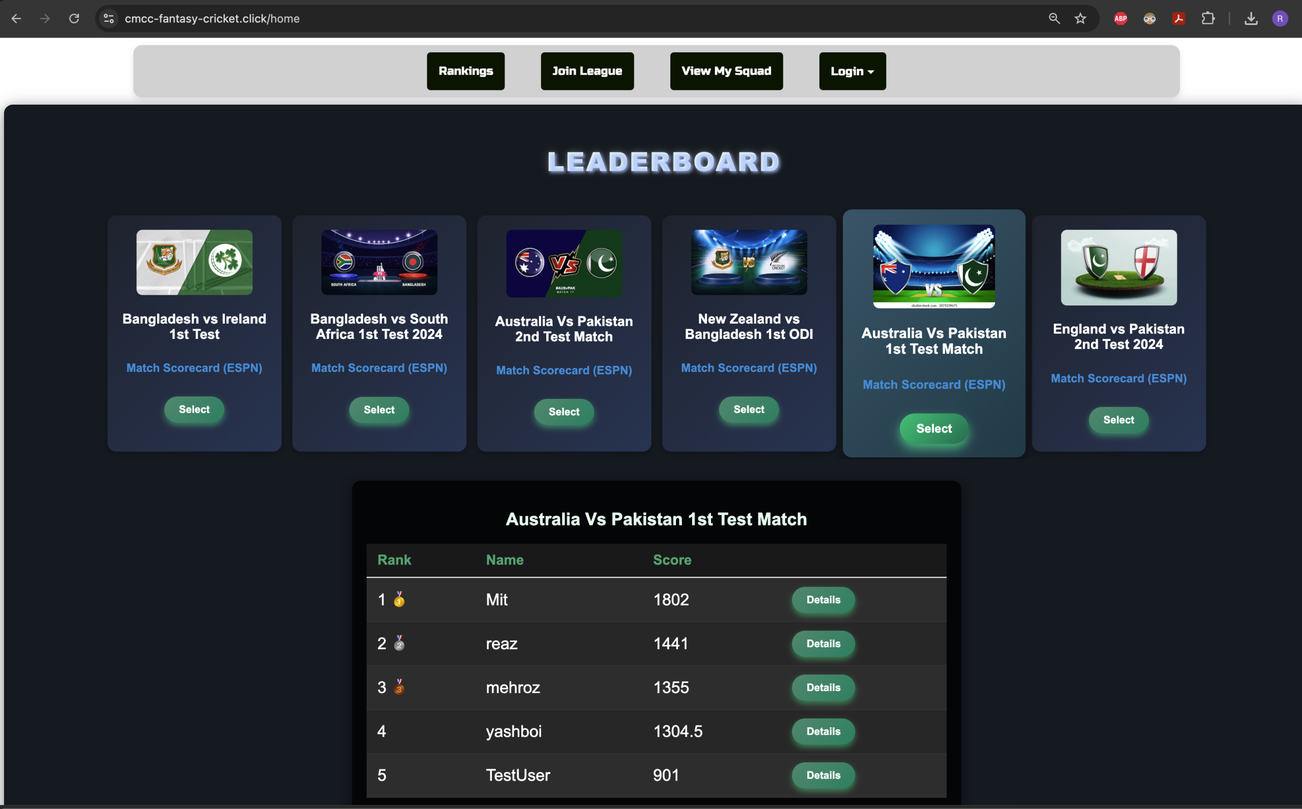
Fantasy Cricket Site (Full Stack)
Live website hosted in AWS: https://cmcc-fantasy-cricket.click/
Github repository for UI written in Angular/TS: https://github.com/reazwrahman/fantasy_ui_angular
Github repository for UI facing micro-service: https://github.com/reazwrahman/fantasy_contest_api_new
Github repository for a backend micro-service (ETL): https://github.com/reazwrahman/Fantasy_Cricket_Backend_Lambda
Building My Fantasy Cricket Website: A Journey from Monolithic to Serverless Architecture
As a cricket enthusiast, I’ve always enjoyed playing fantasy cricket with my friends from high school. However, many of the fantasy cricket websites we used initially offered free services but eventually started charging for their features. Not wanting to pay just to enjoy a game we loved, I decided to take matters into my own hands and build a fantasy cricket website myself.
The Initial Build: A Monolithic Application
When I began this project, I didn’t know much about web development, but I was eager to learn. My first version of the site was a monolithic application, and I deployed it on the Heroku platform. Heroku was a great starting point because it allowed me to get my project online quickly. However, after a while, Heroku started charging me $5 a month. This led me to look for a more cost-effective solution, so I decided to migrate my website to AWS, where it now runs with minimal costs—only $0.50 a month for top-level CNAME redirection.
Phase One: Running on AWS with Elastic Beanstalk
The initial AWS deployment involved running my monolithic application on a single EC2 instance. I used AWS Elastic Beanstalk to manage the application, and an RDS MySQL database for storing all the data. While this setup worked, I noticed that the site had slow response times, which affected the user experience. Additionally, the cost of running EC2 and RDS instances 24/7 was higher than I wanted to pay, which prompted me to rethink my architecture.
Phase Two: Transition to a Serverless Architecture
To reduce costs and improve efficiency, I moved away from the EC2 instance and Elastic Beanstalk. Instead, I opted for a serverless architecture using AWS Lambda functions paired with a MySQL database. This setup allowed me to eliminate the need for always-on instances, theoretically reducing costs and improving scalability. However, I soon discovered that the Lambda-based architecture had performance issues, with response times significantly slower than those of the EC2-based setup. This led me to the next phase of re-architecting.
Phase Three: Enhancing Performance with Micro-services
Determined to improve the performance of my site, I further broke down the architecture into smaller components. I replaced the MySQL database with AWS DynamoDB, a NoSQL database known for its speed and scalability. This change, along with optimizing my use of Lambda functions, resulted in a significant improvement in response times. The current version of the website is now lightning fast, providing a much better user experience than before. Also, in this phase I decided to re-architect my source code: I broke down the monolithic application into two separate micro-services. This eliminated the need for real time computation with each user request and allowed me to run the heavy computation on a regular schedule with a different micro-service. This new architecture increased the performance of the website dramatically.
Phase Four: Upgrading the Front-End
While the back-end of the site is now optimized, the next focus was on improving the front-end. The legacy front-end was built using Python Flask, which had served me well for a prototype. However, to enhance the user experience and modernize the interface, redesigned the front-end using HTML, CSS, TypeScript, and Angular. The goal was to keep Flask as the back-end REST API while using Angular for a more responsive and interactive user interface.
Conclusion
This journey of building my fantasy cricket website has been a tremendous learning experience. From starting with a monolithic application to migrating to a serverless architecture and optimizing with DynamoDB, I’ve learned a lot about web development, cloud architecture, and performance optimization. I’m excited to continue enhancing the site, making it a top-notch platform for fantasy cricket enthusiasts like me and my friends.
-
DIY Thermostat (Full Stack)
Publicly available site:
https://reazwrahman.github.io/thermostat_frontend/Hardware Setup for some perspective: https://reazwrahman.github.io/thermostat_frontend/background_pages/hardware_page/index.html
Github Repository for frontend component: https://github.com/reazwrahman/thermostat_frontend/tree/main
Github Repository for backend component: https://github.com/reazwrahman/Thermostat_Backend_API
Github Repository for simulation component: https://github.com/reazwrahman/SmartThermostat_Simulation
Project Description
In my quest to create a comfortable living environment during the harsh New York winters, I embarked on a project to build a smart heater controller. The heating system in my old single-family house has always been unpredictable, swinging between unbearably hot during the day and freezing cold at night. Manually turning my electric heater on and off to maintain a comfortable temperature became a tedious routine, especially waking up in the middle of the night to adjust it. To solve this, I decided to automate the temperature control in my room using a blend of modern technology and custom-built components.
Project Components: Frontend, Backend, and Two Modes of Operation
My solution is composed of three key components: a frontend user interface, a backend API, and two distinct modes of operation—simulation and target.
1. Frontend: User Interface Built with Modern Web Technologies
To control and monitor the heater system, I built a user-friendly interface from scratch using HTML, CSS, JavaScript, and React. This frontend acts as the control panel for my smart heater, allowing me to set temperature preferences, switch between modes, and view real-time data. The frontend communicates directly with the backend API, sending commands and receiving updates to manage the heater effectively.
2. Backend API: Python and Flask for Flexibility and Control
The backend of the system is built using Python and the Flask framework, which provides a robust and flexible platform for handling the heater control logic. The backend API serves as the brain of the operation, processing inputs from the frontend and managing the heater’s state. It supports two different modes of operation:
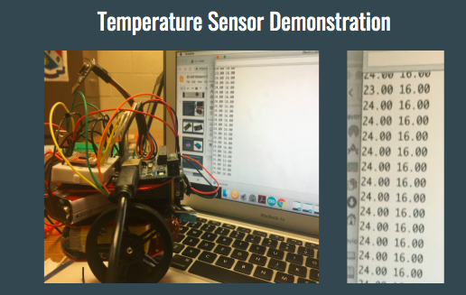
- Simulation Mode: In this mode, the system simulates the entire setup on a computer without needing physical hardware. I created virtual components, including a simulated temperature sensor and a power relay, to mimic real-world conditions. This mode generates logs and test data automatically during runtime, allowing me to validate and fine-tune the system’s behavior without risking actual hardware.
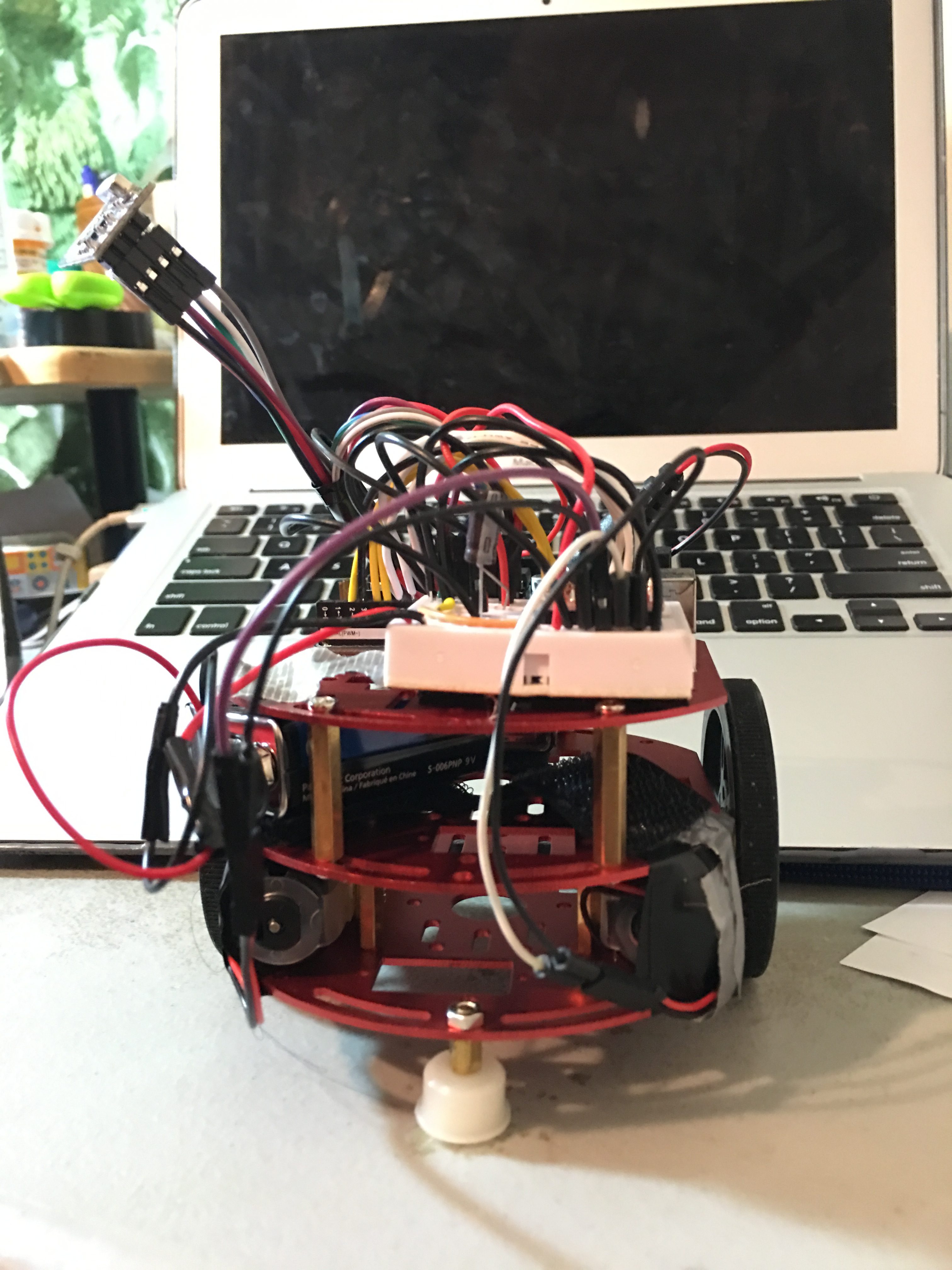
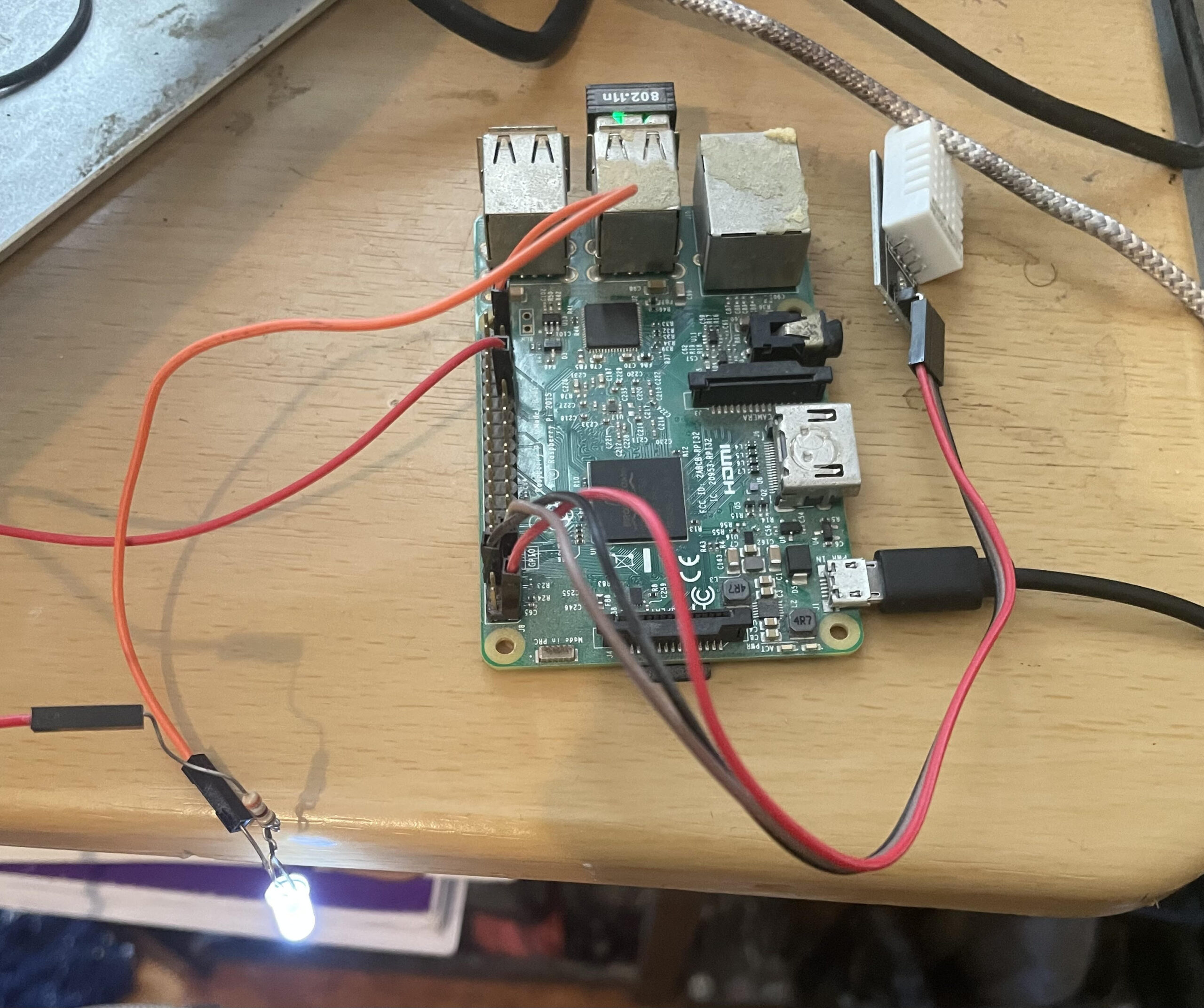
- Target Mode: This is the production-ready setup where real hardware components are involved. In target mode, the system uses a Raspberry Pi microcontroller connected to an actual temperature sensor and a 120-volt power relay. These components control an electric heater or air conditioner, depending on the temperature requirements. The Raspberry Pi handles the processing and communicates with the backend API to ensure accurate temperature regulation in real-time.
Conclusion: A Smarter, More Comfortable Living Space
With these components, my smart heater controller project effectively automates the heating process in my room, adapting to changing temperatures throughout the day and night without requiring manual intervention. Whether running in simulation mode for testing or target mode for real-world application, this system provides a reliable and flexible solution to the challenges of living with an outdated heating system. By integrating modern web technologies with practical hardware solutions, I’ve created a comfortable and efficient living space that keeps me warm on even the coldest New York nights.

A sample page from the website:

-
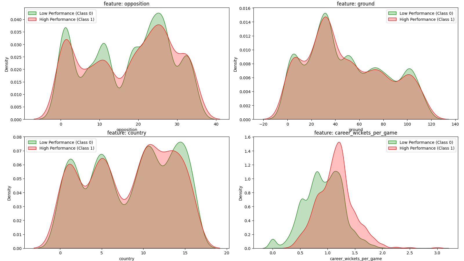
Machine Learning Prediction for Cricket Performance
Project Scope
This repository analyzes a number of machine learning models designed to predict whether a cricket player (batter and bowler) will exceed a specific performance threshold in upcoming matches. The project leverages open source historical data on players’ performances in each individual game and extracts the most relevant features including runs scored, strike rates, recent performance in the last ‘N’ games and match conditions, to train various classification models such as logistic regression, Random Forest, GBM, KNN and SVM.
The analysis is focused around a) finding the right feature combinations for each classifier and b) coming up with a ranking system to compare the performance of the classifiers based on Accuracy, TPR and TNR.
Github Repository: https://github.com/reazwrahman/ML-prediction-for-cricket/tree/main
Youtube Presentation Link: https://www.youtube.com/watch?v=IfC2IZdt6nU
source data: https://data.world/cclayford/cricinfo-statsguru-data
-
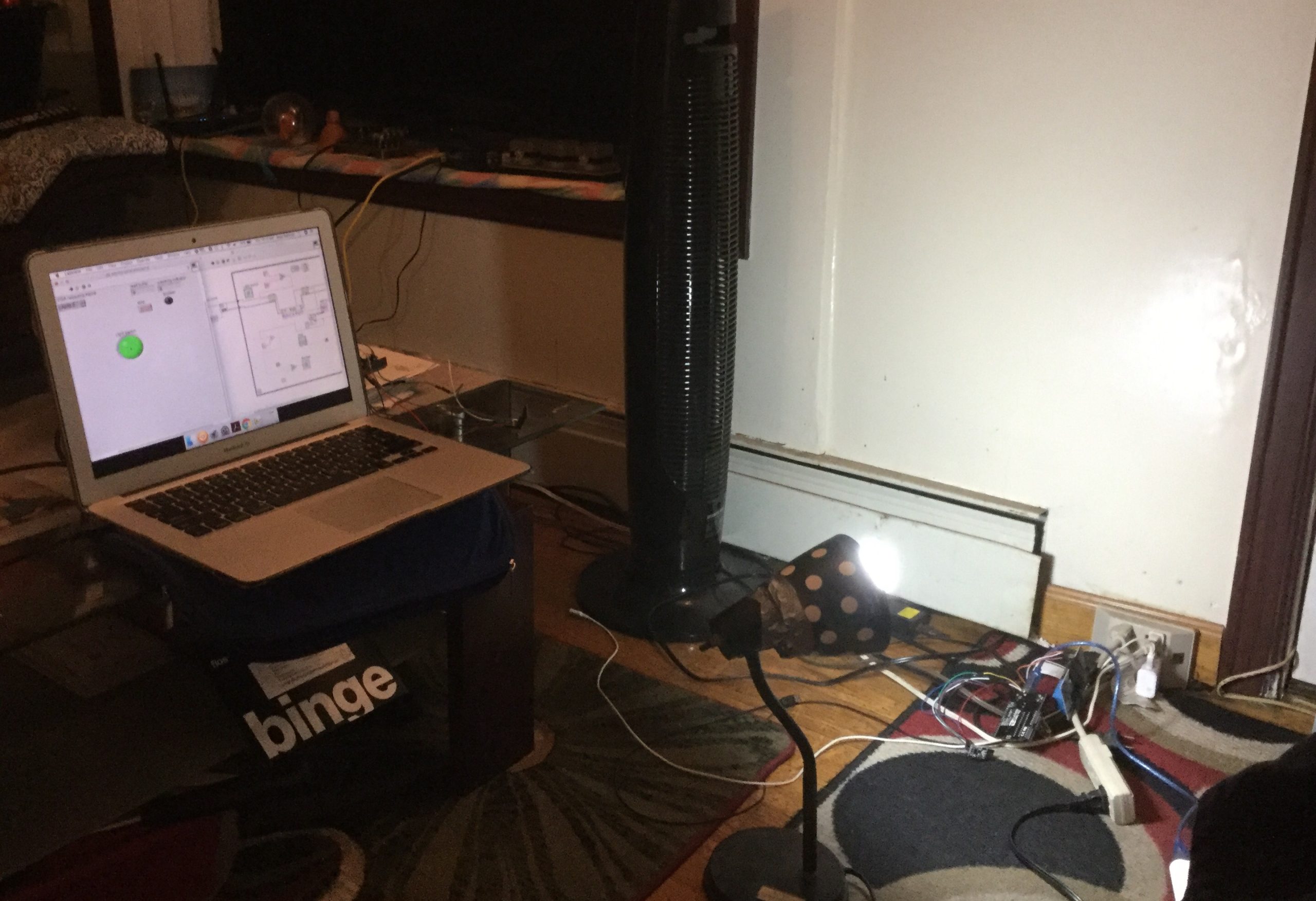
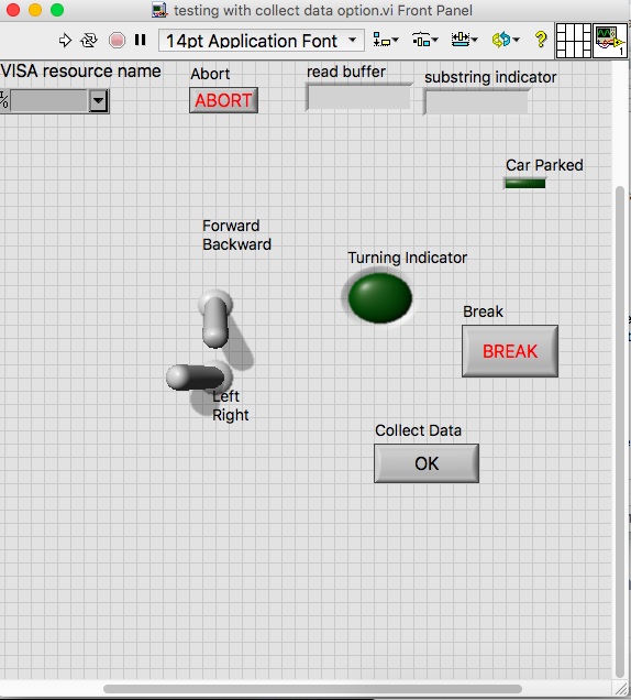
Smart Lamp 2.0 (Radio Freq. Monitoring via LABVIEW VI)

LABVIEW User Interface The user interface above shows the bidirectional capability of the smart lamp. While the toggle switch on the left can be controlled by the user to remotely turn the lamp on and off, the indicator light on the right part of the UI shows the current status of occupancy. If the room containing the lamp is occupied, the motion sensor will activate and send a signal via the radio channel. The receiver radio module will then receive and process the signal so that the indicator light goes on. This UI offers the user to either control the lamp or monitor the room containing the lamp- all remotely via radio frequency.
The video below shows the control of a 120V lightbulb using the native LabVIEW VI application.
A few development pictures are shown below including the LabVIEW application with the logic diagram side by side.


LabVIEW App with logic circuit side by side -
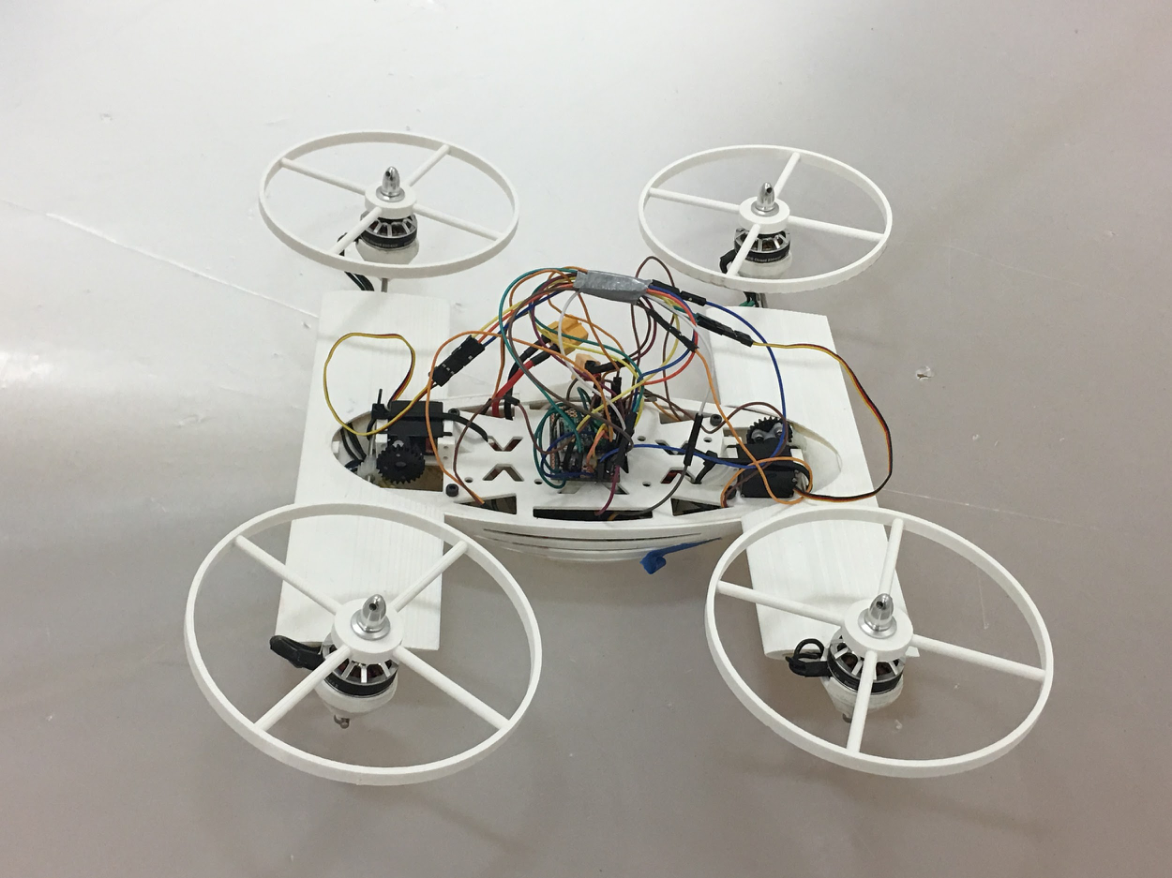
Transformable UAV Project at Texas A&M University
In the Advanced Vertical Flight Laboratory of Texas A&M University, I worked on developing a transformable quad-tilt rotor vehicle during my summer of 2018. This vehicle has four rotors that can be tilted during flight and after landing. Once the four rotors tilt after landing, it virtually becomes a land rover and that’s why it’s called a two-terrain transformable vehicle.
I worked on all the hardware components of this vehicle from the scratch. I also fully developed and tested an embedded C code and a LabVIEW VI code to remotely transform the vehicle from one mode to another. By the end of the summer, I was able to show that my hardware and software combinations are fully functional and I had just enough time to assemble the vehicle and operate it in the land mode.
Drive Mode Video:
Flight Mode Video:

Image: Fully assembled vehicle in both land mode and flight mode orientation
DEVELOPMENT STAGES

Transformation between modes using LabVIEW (my changes are highlighted) 
Testing Full Drive mode on my bench-top setup using RC device 
Power and Control Circuit Testing 
Flight Mode Activated Remotely with a switch 
Drive Mode enabled remotely with a LabVIEW switch -
Electrical Engineering Intern at Lampix Consumer Electronics
At Lampix, we are building an Augmented Reality device that can turn any surface into an interactive screen with a proprietary software for object recognition and machine learning. Our software team is based in Romania. In our New York branch, we have our hardware lab and marketing operations. I am the only electrical engineer working in the hardware lab currently, along with two other mechanical engineers. While the mechanical engineers are responsible for designing the exterior of the device and sourcing mechanical components, my job entails optimizing all the electrical circuit performance, testing circuit parameters and sourcing electrical parts. Below I will list some of my accomplishments in this role:
Latest PCB Design: This is the final version of my designed PCB. This circuit board will supply power in 5V, 12V and 19V rails. It incorporates embedded switchers from TI, Transistors and load switch. The embedded switchers are well researched, designed and simulated in TI WEBENCH before implementing in a CAD design.


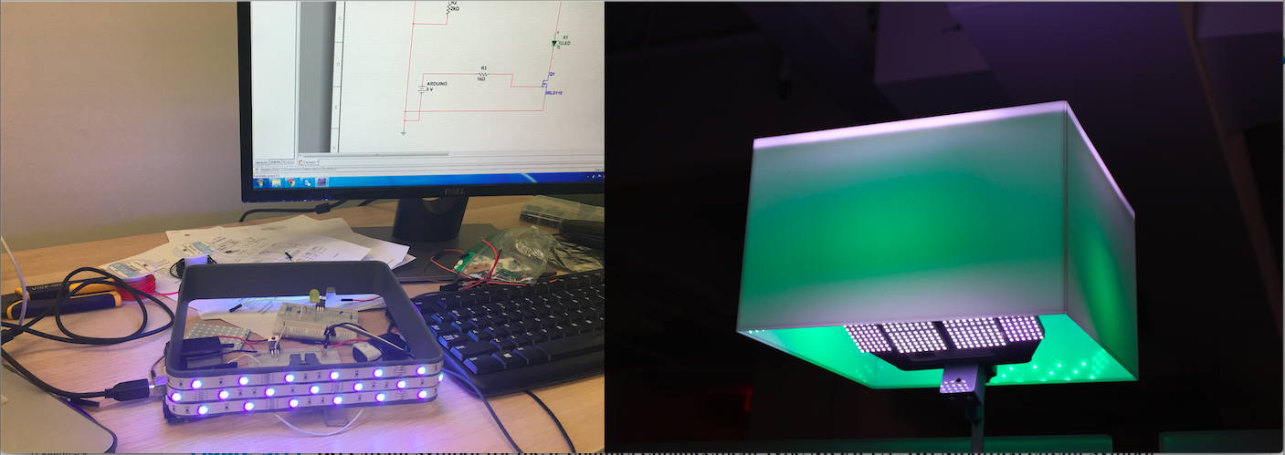
Pulse Width Modulation: I have designed a pulse width modulation protocol for a dynamic RGB LED appearance by controlling and varying the light color and appearance of our augmented reality device. Upon a request from our marketing team, I have devised this module for enhancing the visual aesthetic of the product. The RGB Led strip is powered by a DC 12V source. There are three independently controlled MOSFETs that dictate the operation of each color. The duty cycle of the LEDs are controlled via an Intel microprocessor. I wrote the python code for running this RGB PWM.


PCB Design: Inside our augmented reality device we have a power circuit that was initially a wired connection. My job was to convert this wired circuit into an integrated PCB model. So, far I have created two prototypes. The next and final prototype is aimed to eliminate all the wired connection and it is to be used in our five hundred product run. I spent my first week at work understanding the circuit and developing a manual prototype for how the PCB should look like on a Veroboard by soldering the components manually. This handmade prototype was a green light for my PCB design to send out to a fabrication house.


First PCB Model:

This simple PCB model was my first prototype to understand all the moving parts and it was sent for printing within my second week at work. It encompasses a power and ground rail, two step-down buck converters, pins for a DC Power Jack, a switch and holes for connecting the power pins of a projector.
The printed product looks like this:

Although it’s rudimentary, the board was able to eliminate most of the wired connections.
Second PCB Model: The second model is more robust and sophisticated as it replaces the previously used step down buck converters with TI’s embedded power switchers. I have researched, tested and simulated my power circuit design with TI WEBENCH and then converted the design into Eagle Schematic for turning it into a PCB model.


Image: Power Circuit Design, BOM and Simulation in TI WEBENCH
I have designed a way to incorporate a universal switch that can easily turn on/off all the components with a single user input.

-
Smart Home Security (Personal Project)
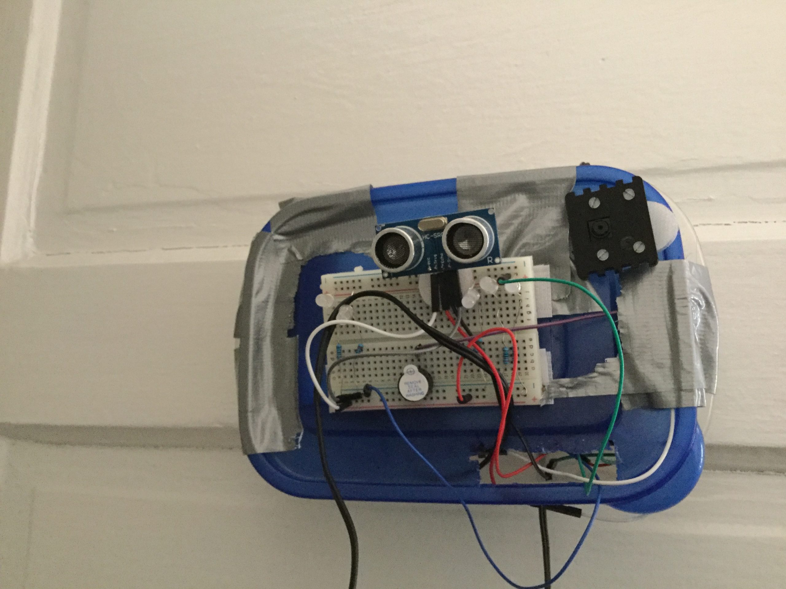
Project Home Security is a hardware and software combination project that detects the presence of an intruder outside the front door of a house and immediately sends an email alerting the user about the activity with a picture of the person standing outside.

Image: Ultrasonic sensor placed outside the door to detect activity

Image: Screenshot of the email sent by the server with a message alerting the user, with a picture taken by the camera

Image: Control System inside the house, near the front door (the TV monitor could be used for surveillance purposes)
This project uses an ultrasonic sensor, wires, Arduino, raspberry pi, ethernet cable and an interface for Pi/Arduino for initial setup. The ultrasonic sensor may be replaced by a body motion sensor (for shorter range setup), which actually was used for this project initially. However, as the connecting wires get longer- the body motion sensor starts acting in unanticipated ways.

Image: I added a camera interface for taking picture of the intruder
The Arduino board establishes a connection with the ultrasonic sensor. As the distance read by the sensor gets below a certain threshold, it prints a message which is then received by the raspberry pi connected to the Arduino via a USB serial port.

Image: I added LEDs for taking picture at night
As the raspberry receives the message, an SSMTP messaging protocol relays that message to an email address. The user can add that email account to their existing Gmail app and receive notifications about the front door activity in real time.
Here are some pictures that were taken during the development stage of the product:

-
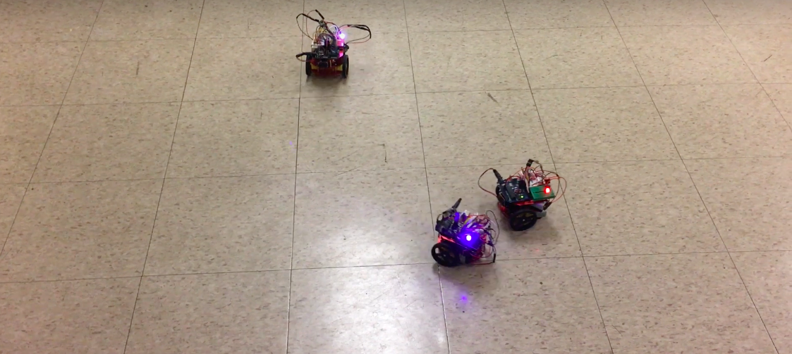
Swarm Robotics via RF communication
The Video below shows wireless communication between two computers. The one on the right is the user interface that will be used to operate the swarms. The computer on the left is the receiver that shows the message received.
I also created a user interface to remotely control the swarms using RF.
LabVIEW UI 
These swarm robots are capable of collecting data from the field of operation using different sensors and send these data back to the master device remotely in real time.