Category: Hardware Projects

Hardware Projects

  • Electrical Engineering Intern at Lampix Consumer Electronics

    Electrical Engineering Intern at Lampix Consumer Electronics

    At Lampix, we are building an Augmented Reality device that can turn any surface into an interactive screen with a proprietary software for object recognition and machine learning. Our software team is based in Romania. In our New York branch, we have our hardware lab and marketing operations. I am the only electrical engineer working in the hardware lab currently, along with two other mechanical engineers. While the mechanical engineers are responsible for designing the exterior of the device and sourcing mechanical components, my job entails optimizing all the electrical circuit performance, testing circuit parameters and sourcing electrical parts. Below I will list some of my accomplishments in this role:     

    Latest PCB Design: This is the final version of my designed PCB. This circuit board will supply power in 5V, 12V and 19V rails. It incorporates embedded switchers from TI, Transistors and load switch. The embedded switchers are well researched, designed and simulated in TI WEBENCH before implementing in a CAD design.


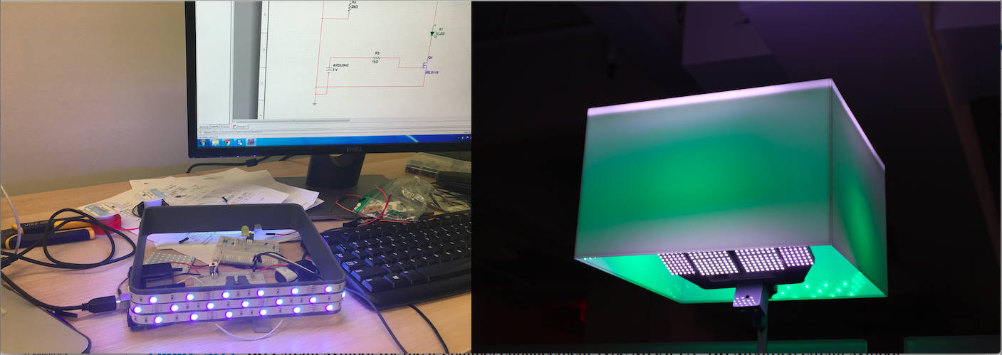
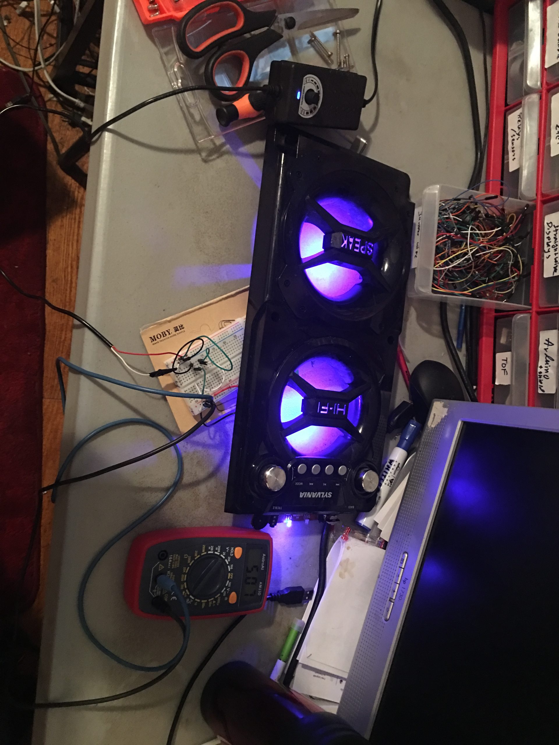
    Pulse Width Modulation: I have designed a pulse width modulation protocol for a dynamic RGB LED appearance by controlling and varying the light color and appearance of our augmented reality device. Upon a request from our marketing team, I have devised this module for enhancing the visual aesthetic of the product.  The RGB Led strip is powered by a DC 12V source. There are three independently controlled MOSFETs that dictate the operation of each color. The duty cycle of the LEDs are controlled via an Intel microprocessor. I wrote the python code for running this RGB PWM. 


    PCB Design: Inside our augmented reality device we have a power circuit that was initially a wired connection. My job was to convert this wired circuit into an integrated PCB model. So, far I have created two prototypes. The next and final prototype is aimed to eliminate all the wired connection and it is to be used in our five hundred product run. I spent my first week at work understanding the circuit and developing a manual prototype for how the PCB should look like on a Veroboard by soldering the components manually. This handmade prototype was a green light for my PCB design to send out to a fabrication house. 


    First PCB Model:    


    This simple PCB model was my first prototype to understand all the moving parts and it was sent for printing within my second week at work. It encompasses a power and ground rail, two step-down buck converters, pins for a DC Power Jack, a switch and holes for connecting the power pins of a projector.

    The printed product looks like this: 

    Although it’s rudimentary, the board was able to eliminate most of the wired connections.

    Second PCB Model:   The second model is more robust and sophisticated as it replaces the previously used step down buck converters with TI’s embedded power switchers. I have researched, tested and simulated my power circuit design with TI WEBENCH and then converted the design into Eagle Schematic for turning it into a PCB model.  

    Image: Power Circuit Design, BOM and Simulation in TI WEBENCH

    I have designed a way to incorporate a universal switch that can easily turn on/off all the components with a single user input. 


  • BJT Audio Amplifier

    BJT Audio Amplifier

    This is an audio amplifier that takes a small AC input signal from 3.5mm Audio Jack and powers up a 8 ohm speaker through a series of signal and power amplifier. The design includes two signal amplifier circuit, followed by a power amplifier. It operates on a 12V dc source. Each amplifier is simulated in Multisim- all the DC operating points and transient analysis is performed by Multisim and confirmed by manual calculations using SparkView and a four channel Oscilloscope.


  • Solar Hydrogen MicroPowerplant (Research Project)

    Solar Hydrogen MicroPowerplant (Research Project)

    PROJECT DESCRIPTION

    This project investigates the fusion of hydro-kinetic energy generated by a series of in-pipe water turbines and electric energy gained from a series of solar panels. This combined energy source is applied to break down rainwater into hydrogen and oxygen form. This micro energy unit could be a potential resolution to the energy crisis in developing countries by producing energy from natural elements such as rainfall and/or sunlight.  In my research, I have studied and tested my hypotheses correlating the production of hydrogen and oxygen with different varying constructional components. In my model, I used a water turbine setup at the bottom of rain gutters that had a direct access to the rainwater collected on the rooftop of a building. The kinetic energy generated by the vertical flow of rainwater through the pipe causes the water turbine to rotate which in turn generates electrical energy. This hydrokinetic energy source is combined with a series of solar panels to produce enough electrical power to accomplish the hydrolysis reaction.  In my laboratory experiments, my micro-model consisted of a 3 V solar panel, a 3 V motor with the water turbine, and a 3 V hydrogen fuel cell.

    Image: A complete simulation of the project designed in Autodesk Inventor 2015


    Image: A motor attached to water turbine (designed via Autodesk Inventor 2015)

    Image: Prototype Prepared for Engineering Research Competitions

    Image: A solar panel designed in Autodesk Inventor Professional 2015

    Image: In-pipe water turbine designed in Autodesk Inventor 2015

    Image: A prototype of a water turbine made in Brooklyn Tech Robotics Workshop


  • Redesigning the Power Circuit for a Bluetooth Speaker

    Redesigning the Power Circuit for a Bluetooth Speaker

    This project was born out of necessity. My Bluetooth speaker stopped working all on a sudden. I opened up the speaker, found the PCB and noticed that the 5V DC jack is broken and as a result, it’s not charging anymore.

    I spent some time studying the PCB, tracing the PCB routes and realized that the DC jack was designed to get power from a continuous supply and it charges a 3.7V(1200 mAh) Li-Po battery. The battery is then connected to all the components on the printed circuit board. I decided to remove the battery, extend the power wires from the speaker and directly solder them to a 5V continuous DC supply. Although the speaker lost its portability due to this redesigned model of the power circuit, I was able to fix it without buying any additional component. Plus, my use of the speaker is almost always stationary.

    Image: exposed PCB after opening the speaker 

    Broken DC Jack
    TESTING MY SOLUTION WITH A BREADBOARD PROTOTYPE. I ALSO FOUND OUT THE MINIMUM AND MAXIMUM VOLTAGE I CAN SUPPLY SAFELY.

    REDESIGNED POWER CIRCUIT WITH A DIRECT 5V CONNECTION (MANUALLY SOLDERED)                             
    FINAL WORKING VERSION OF THE SPEAKER