Publicly available site:
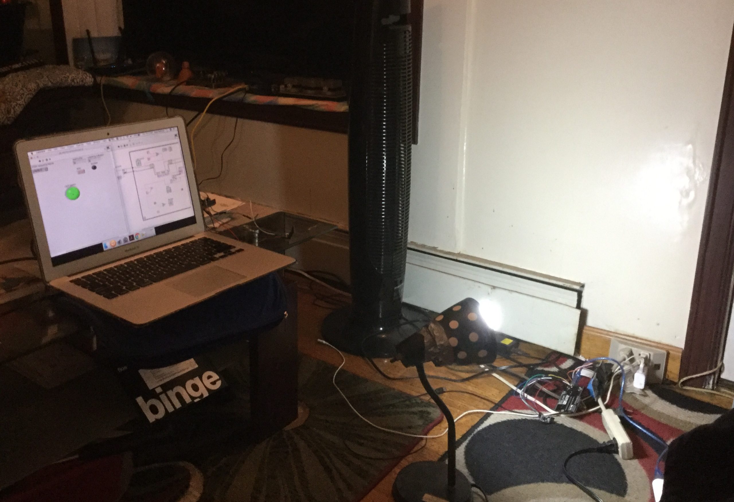
https://reazwrahman.github.io/thermostat_frontend/Hardware Setup for some perspective: https://reazwrahman.github.io/thermostat_frontend/background_pages/hardware_page/index.html
Github Repository for frontend component: https://github.com/reazwrahman/thermostat_frontend/tree/main
Github Repository for backend component: https://github.com/reazwrahman/Thermostat_Backend_API
Github Repository for simulation component: https://github.com/reazwrahman/SmartThermostat_Simulation
Project Description
In my quest to create a comfortable living environment during the harsh New York winters, I embarked on a project to build a smart heater controller. The heating system in my old single-family house has always been unpredictable, swinging between unbearably hot during the day and freezing cold at night. Manually turning my electric heater on and off to maintain a comfortable temperature became a tedious routine, especially waking up in the middle of the night to adjust it. To solve this, I decided to automate the temperature control in my room using a blend of modern technology and custom-built components.
Project Components: Frontend, Backend, and Two Modes of Operation
My solution is composed of three key components: a frontend user interface, a backend API, and two distinct modes of operation—simulation and target.
1. Frontend: User Interface Built with Modern Web Technologies
To control and monitor the heater system, I built a user-friendly interface from scratch using HTML, CSS, JavaScript, and React. This frontend acts as the control panel for my smart heater, allowing me to set temperature preferences, switch between modes, and view real-time data. The frontend communicates directly with the backend API, sending commands and receiving updates to manage the heater effectively.
2. Backend API: Python and Flask for Flexibility and Control
The backend of the system is built using Python and the Flask framework, which provides a robust and flexible platform for handling the heater control logic. The backend API serves as the brain of the operation, processing inputs from the frontend and managing the heater’s state. It supports two different modes of operation:
- Simulation Mode: In this mode, the system simulates the entire setup on a computer without needing physical hardware. I created virtual components, including a simulated temperature sensor and a power relay, to mimic real-world conditions. This mode generates logs and test data automatically during runtime, allowing me to validate and fine-tune the system’s behavior without risking actual hardware.
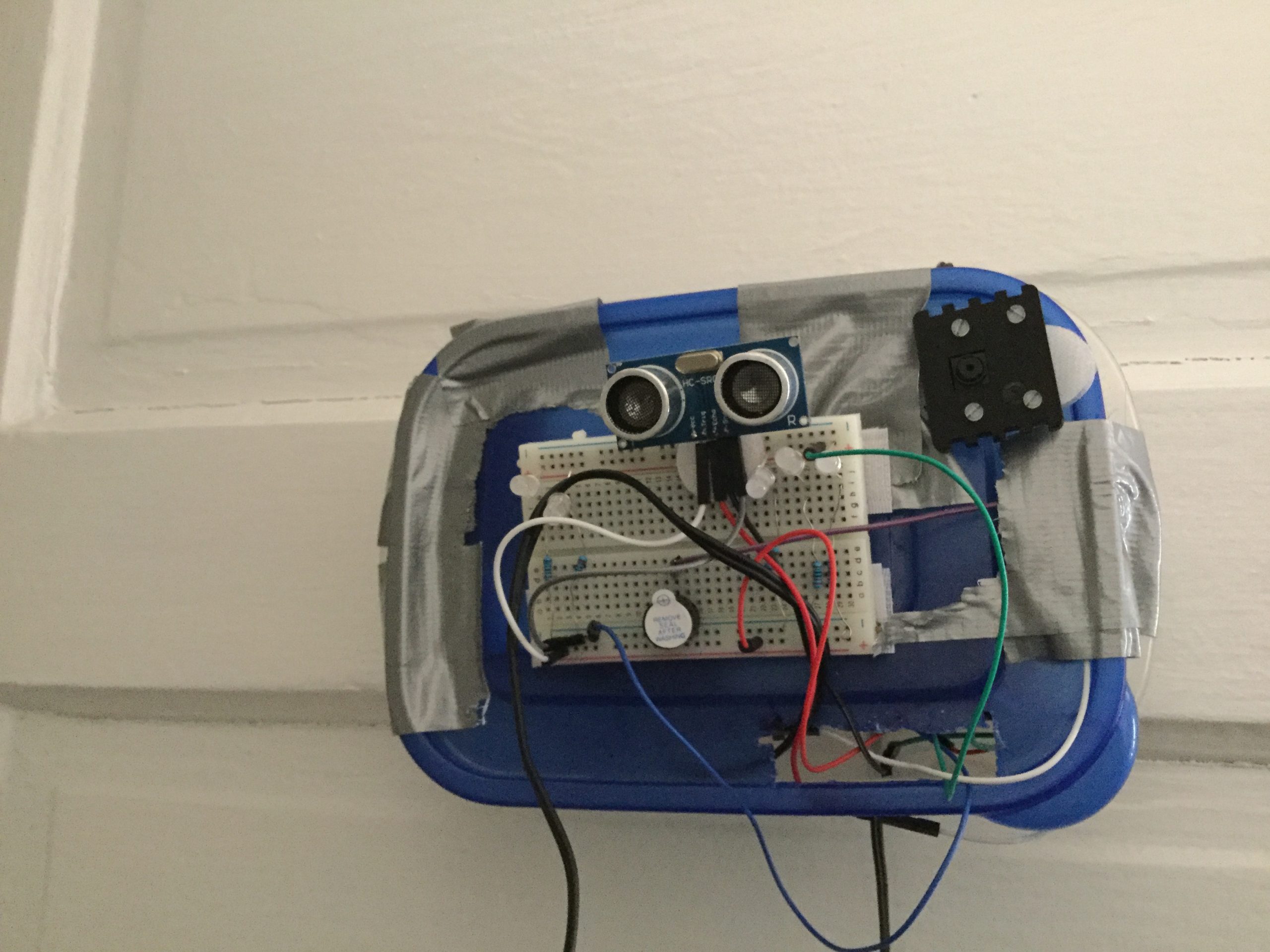
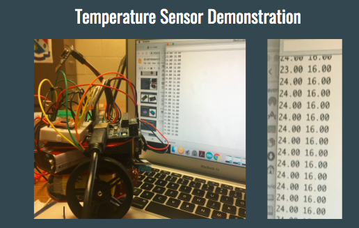
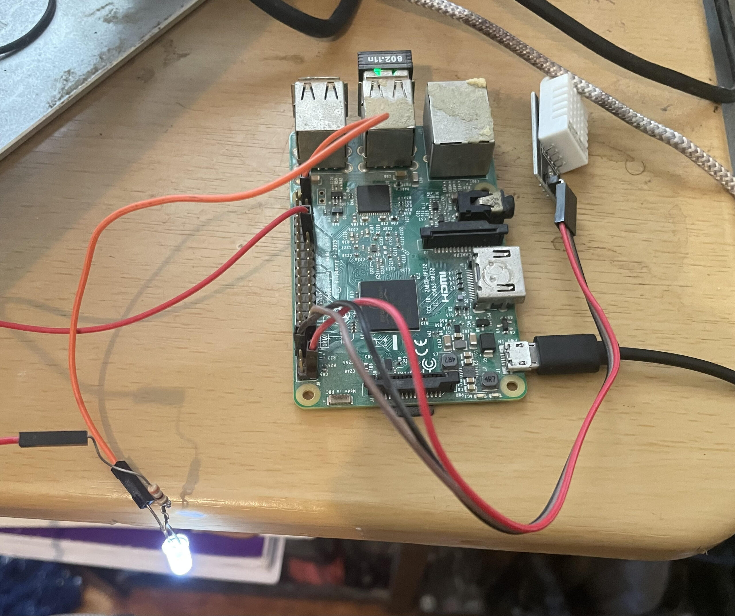
- Target Mode: This is the production-ready setup where real hardware components are involved. In target mode, the system uses a Raspberry Pi microcontroller connected to an actual temperature sensor and a 120-volt power relay. These components control an electric heater or air conditioner, depending on the temperature requirements. The Raspberry Pi handles the processing and communicates with the backend API to ensure accurate temperature regulation in real-time.
Conclusion: A Smarter, More Comfortable Living Space
With these components, my smart heater controller project effectively automates the heating process in my room, adapting to changing temperatures throughout the day and night without requiring manual intervention. Whether running in simulation mode for testing or target mode for real-world application, this system provides a reliable and flexible solution to the challenges of living with an outdated heating system. By integrating modern web technologies with practical hardware solutions, I’ve created a comfortable and efficient living space that keeps me warm on even the coldest New York nights.

A sample page from the website: